USB-C Trigger Board
TL;DR
I made a USB-C trigger board that supplies power to my projects at various voltage and power levels for maximum convenience.
Navigation:
- Stay on this page for overall project description
- Background and Requirements page for info on USB-C and requirements
- Hardware page for component selection and PCB design
- Firmware page for STM32 firmware implementation
Overview
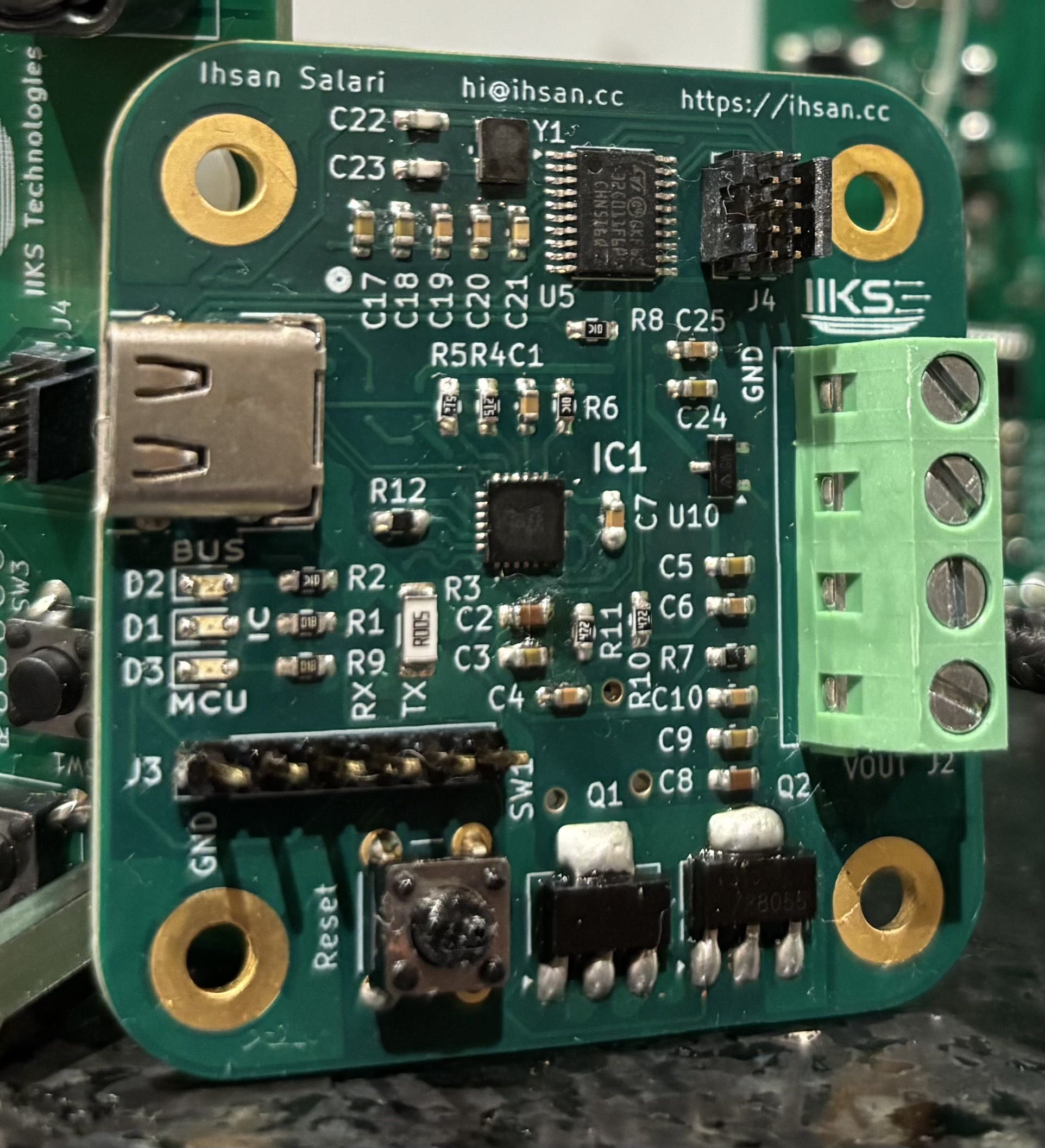
This project is a 140W USB-C trigger board which supports SPR and EPR at both fixed and programmable voltage and current levels using PPS (read the Background and Requirements page if you don't know what this means). The maximum power is 140W with 28V at 5A of current.
The device is small and sports mounting holes for easy securing to various projects and enclosures.
The design is based around the AP33772S, a new PD controller by Diodes Incorporated which supports SPR, EPR, and PPS, all up to 28V. A very basic STM32C0 with 32kB of flash memory is used to communicate with the PD controller via I2C. The PD controller stores available PDOs in registers and the MCU can read and select modes by reading and setting the appropriate addresses.
A UART interface is available for debugging and for selecting voltage levels once the system is up, and a SW-JTAG header is used for programming the STM32 via SW. The power output is connected or disconnected through two MOSFETs driven by the PD controller, and is then available on a 4-slot screw terminal.
For more information, see:
- Background and Requirements page for info on USB-C and requirements
- Hardware page for component selection and PCB design
- Firmware page for STM32 firmware implementation